August 31, 2013
FABRICATION OF ZIRCONIUM DIBORIDE PARTS USING SELECTIVE LASER SINTERING
FREEFORM FABRICATION OF ZIRCONIUM DIBORIDE PARTS
USING SELECTIVE LASER SINTERING
Ming C. Leu, Erik B. Adamek, Tieshu Huang, Greg E. Hilmas and Fatih Dogan
Department of Mechanical and Aerospace Engineering
Department of Material Science and Engineering
Missouri University of Science and Technology
http://edge.rit.edu/edge/P10551/public/SFF/SFF%202008%20Proceedings/Manuscripts/2008-18-Leu.pdf
OPTIMIZATION OF SELECTIVE LASER SINTERING PROCESS FOR
FABRICATION OF ZIRCONIUM DIBORIDE PARTS
Ming C. Leu, Shashwatashish Pattnaik, Gregory E. Hilmas
Department of Mechanical and Aerospace Engineering, Missouri University of Science
and Technology, Rolla, Missouri, USA
Department of Materials Science, Missouri University of Science and Technology,
Rolla, Missouri, USA
http://utwired.engr.utexas.edu/lff/symposium/proceedingsArchive/pubs/Manuscripts/2010/2010-41-Leu.pdf
Selective Laser Sintering ofZirconium Silicate
F. Klocke, H. Wirtz
Fraunhofer Institute ofProduction Technology IPT
Steinbachstr. 17
52074 Aachen
Germany
http://utwired.engr.utexas.edu/lff/symposium/proceedingsArchive/pubs/Manuscripts/1998/1998-69-Klocke.pdf
Rapid Manufacturing of Ceramic Components for Medical and Technical Applications via Selective Laser Melting
Jan Wilkes, Konrad Wissenbach
Fraunhofer Institute for Laser Technology ILT
Steinbachstr. 15, 52074 Aachen, Germany
http://www.rm-platform.com/index2.php?option=com_docman&task=doc_view&gid=438&Itemid=1
3D Printing And Additive Manufacturing-Extending your printing capability in true 3D
Dr. Phil Reeves
Managing Director, Econolyst Ltd, UK
http://www.dezignstuff.com/SolidEdge/306%20-%203D%20Printing%20And%20Additive%20Manufacturing%20Extending%20your%20printing%20capability%20in%20true%203D%20-%20Dr%20Phil%20Reeves.pdf
Kind of Fine ceramic
| ||||
| 알루미나는 파인세라믹 제품의 대표적인 재료로서 내마모성, 내부식성 그리고 절연성이 우수할 뿐만 아니라 다른 재료에 비해서 가격이 저렴하여 많이 사용되고 있습니다. | ||||
| 응용분야 : 수도밸브, 마그네트론용 세라믹, 절삭공구, 메카니컬 실, 산업용 기계 부품 | ||||
| ||||
| 실리콘 나이트라이드는 열충격에 가장 강한 특성을 가지고 있습니다. 또한 내부식성이 뛰어나고 고온 강도가 우수하여 내열 구조재료로 많이 쓰입니다. | ||||
| 응용분야 : 다이스, 절삭공구, 용접용 로케이션 핀, 초정밀볼과 베어링, 자동차엔진용 부품, 내열 부품 | ||||
| ||||
| 지르코니아는 실온에서 기계적 강도가 뛰어나며, 금속에 가까운 인성을 지니고 있습니다. 특히 당사의 지르코니아는 균일하고 미세한 입경을 갖도록 고품질의 초미립 원료를 사용하여 뛰어난 표면조도 등 탁월한 물리화학적 특성을 발현하고 있습니다. | ||||
| 응용분야 : 치아 임플란트 재료, 광통신용 페룰, 각종 액세서리(시계, 넥타이핀), 다이스, 절삭공구, TV브라운관 전자총용 비드 베이스 부품, 세라믹 칼 및 가위 등 | ||||
| ||||
| 실리콘 카바이드는 내식성이 가장 뛰어난 재료입니다. 기계적 강도가 강하고 내마모성이 우수하며, 특히 1,400℃ 정도의 고온에서도 강도를 유지하는 특성이 있습니다. | ||||
| 응용분야 : 메카니컬 실, 노즐, 낚시도구용 가이드, 웨이퍼 플레이트 |
How zirconium is made
Background
Zirconium, symbol Zr on the Periodic Table, is a metal most often found in and extracted from the silicate mineral zirconium silicate and the oxide mineral baddeleyite. In its various compound forms, the grayish-white zirconium is the nineteenth most plentiful element in the earth's crust, where it is far more abundant than copper and lead. It belongs to the titanium family of metals, a group that also includes titanium and hafnium and that is favored in industry for its members' good electrical conductivity as well as their tendency to form metallic salts. Because it is stable in many electron configurations and physical states, zirconium can be made into many products. However, since the 1940s, its most significant applications have been in various structural components of nuclear reactors.
Zirconium was discovered by German chemist Martin Heinrich Klaproth, who first isolated an oxide of the mineral zircon in 1789. The first metallic powder was produced in 1824 by a Swedish Chemist, Jons J. Berzelius. The forms of the metal that could be isolated during the nineteenth century, however, were impure and thus very brittle. The earliest method of purifying useable quantities of the metal was developed in 1925 by Dutch chemists Anton E. van Arkel and J. H. de Boer, who invented a thermal iodide process by which they thermally decomposed zirconium tetraiodide. The drawback with van Arkel and de Boer's method was its cost, but twenty years later William Justin Kroll of Luxembourg invented a cheaper process, using magnesium to break down zirconium tetrachloride. Relatively inexpensive, this process produced zirconium in quantities large and pure enough for industrial use.
Since Kroll's breakthrough, zirconium has become an important element in several industries: steel, iron, and nuclear power. It is used in the steel industry to remove nitrogen and sulfur from iron, thereby enhancing the metallurgical quality of the steel. When added to iron to create an alloy, zirconium improves iron's machinability, toughness, and ductility. Other common industrial applications of zirconium include the manufacture of photoflash bulbs and surgical equipment, and the tanning of leather.
Despite its ability to be used for many different industrial applications, most of the zirconium produced today is used in water-cooled nuclear reactors. Zirconium has strong corrosion-resistance properties as well as the ability to confine fission fragments and neutrons so that thermal or slow neutrons are not absorbed and wasted, thus improving the efficiency of the nuclear reactor. In fact, about 90 percent of the zirconium produced in 1989 was used in nuclear reactors, either in fuel containers or nuclear product casings.
Raw Materials
Of the two mineral forms in which zirconium occurs, zircon is by far the more important source. Found mainly in igneous rock, zircon also appears in the gravel and sand produced as igneous rock erodes. In this form, it is often mixed with silica, ilmenite, and rutile. The vast majority of the zircon used in industry today originates in these sand and gravel deposits, from which the purest zircon is extracted and refined to be used as zirconium metals. Less pure deposits are used in the form of stabilized zirconia for refractories and ceramic products. The world's largest zircon mines are in Australia, South Africa,
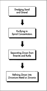
The sand and gravel that contain zircon are typically collected from coastal waters by a floating dredge, a large steam shovel fitted on a floating barge. After the shovel has scooped up the gravel and sand, they are purified by means of spiral concentrators, and then unwanted material is removed by magnetic and electrostatic separators.
End-product manufacturers of zircon further refine the nearly pure zircon into zirconium by using chlorine to purify the metal and then sintering (heating) it until it becomes sufficiently workable for industrial use. Less-pure zircon is made into zirconia, an oxide of zirconium, by fusing the zircon with coke, iron borings, and lime until the silica is reduced to silicon that alloys with the iron.
End-product manufacturers of zircon further refine the nearly pure zircon into zirconium by using chlorine to purify the metal and then sintering (heating) it until it becomes sufficiently workable for industrial use. Less-pure zircon is made into zirconia, an oxide of zirconium, by fusing the zircon with coke, iron borings, and lime until the silica is reduced to silicon that alloys with the iron.
Extraction and Refining
Extracting zircon
- 1 The sand and gravel that contain zircon mixed with silicate, ilmenite, and rutile are typically collected from coastal waters by a floating dredge, a large steam shovel fitted on a floating barge. After the shovel has scooped up the gravel and sand, they are purified by means of spiral concentrators, which separate on the basis of density. The ilmenite and rutile are then removed by magnetic and electrostatic separators. The purest concentrates of zircon are shipped to end-product manufacturers to be used in metal production, while less pure concentrations are used for refractories.
Refining zircon
- 2 End-product manufacturers of zircon further refine the nearly pure zircon into zirconium by using a reducing agent (usually chlorine) to purify the metal and then sintering (heating) it until it becomes sufficiently ductile—workable—for industrial use. For small-scale laboratory use, zirconium metal may be produced by means of a chemical reaction in which chloride is used to reduce the zircon.
- 3 The less-pure zircon is made into zirconia, an oxide of zirconium, by fusing the zircon with coke, iron borings, and lime until the silica is reduced to silicon that alloys with the iron. The zirconia is then stabilized by heating it to about 3,095 degrees Fahrenheit (1,700 degrees Celsius), with additions of lime and magnesia totalling about five percent.
Refining baddeleyite
- 4 As mentioned above, baddeleyite contains relatively high, pure concentrations of zirconium oxide that can be used without filtering or cleansing. The only refining process used on baddeleyite involves grinding the gravel or sand to a powder and sizing the powder with different sized sieves. All zirconium oxide that comes from baddeleyite is used for refractories and, increasingly, advanced ceramics.
Quality Control
The quality control methods implemented in the production of zirconium metal are typical Statistical Process Control (SPC) methods used in most metal production. These involve tracking and controlling specific variables determined by the end product requirements. Stringent government quality control is applied to all zirconium metal produced for nuclear applications. These controls assure that the zirconium produced for use in a nuclear plant has been processed correctly and also allow for accountability: processing is tracked so that it can be traced back to each individual step and location.
Quality control methods for zirconium used in refractory applications also focus on SPC. However, in the refractory industries, it is also necessary to ascertain the beach (and even what part of the beach) from which the zirconium mineral was extracted. Manufacturers need to know exactly where the zirconium came from because each source contains slightly different trace elements, and different trace elements can affect the end product.
Byproducts/Waste
Silicate, ilmenite, and rutile—all byproducts of the zircon refining process—are typically dumped back in the water at the extraction site. These elements compose typical beach sand and are in no way detrimental to the environment. Magnesium chloride, the only other notable byproduct of zirconium manufacturing, results from the reduction of the zircon with chlorine in the refining process and is typically sold to magnesium refineries. No byproducts or waste result from baddeleyite refining.
The Future
Many believe that the future of zirconium lies in its use as an advanced ceramic. Advanced ceramics—also called "fine," "new," "high-tech," or "high-performance" ceramics—are generally used as components in processing equipment, devices, or machines because they can perform many functions better than competing metals or polymers. Zirconium is fairly hard, doesn't conduct heat well, and is relatively inert (i.e., it doesn't react readily with other elements), all excellent qualities for advanced ceramics. Zirconium oxide, manufactured as a ceramic, can be used to make crucibles for melting metals, gas turbines, liners for jet and rocket motor tubes, resistance furnaces, ultra-high frequency furnaces, and refractories such as the facing of a high-temperature furnace wall.
Where To Learn More
Books
Heuer, A. H., ed. Science and Technology of Zirconia. American Ceramic Society, 1981.Specifications for Zirconium and Zirconium Alloy Welding Electrodes and Rods. American Welding Society, 1990.
Zirconium and Hafnium. Gordon Press Publishers, 1993.
Periodicals
Burke, Marshall A. "Ceramics Enter the Foundry," Design News. June 16,1986, p. 56."Fuel Cell's Future Gets a Boost," Design News. August 18, 1986, p. 38.
"Zirconium," Machine Design. April 14, 1988, pp. 234-35.
"Zirconium Holds Down Costs of Making Zirconium," Metal Progress. November, 1983, pp. 11-12.
"Adding Strength to Glassy Ceramics," Science News. September 13, 1986, p. 170.
— Alicia Haley and
Blaine Danley
Blaine Danley
Read more: http://www.madehow.com/Volume-1/Zirconium.html#ixzz2dXqMVgkb
source http://www.madehow.com/Volume-1/Zirconium.html
Focus SLS printer
Focus is a 3D printer that is designed to print using Selective Laser Sintering. Focus can also be adapted for FDM, 3DP and lasercutting/engraving.
http://www.thingiverse.com/thing:33697
http://focussls.blogspot.nl/
http://www.instructables.com/id/Focus-an-experimental-powder-printing-platform/
August 23, 2013
PBP(3DP™) :: Powder Bed and inkjet head 3d Printing
3d 프린터가 쏘아올린 미래 혁명
가정용 3D 프린터의 개발과 보급을 바라보며 기껏해야 DIY 마니아를 위한 부품 제조기, 혹은 부러진 머그컵 손잡이를 만드는 기계 정도로 여겼나? 그랬다면 오산이다. 3D 프린터의 잠재력이 도대체 어디까지인지, 그리고 3D 프린터가 우리의 삶에 미칠 파괴력이 어느 정도인지 짐작케 할 사건이 최근 벌어졌다.
3D 프린터로 실제 발사와 살상이 가능한 권총이 제작된 것. 게다가 그 설계도가 인터넷에 공개되기까지 했다. 3D 프린터로 인한 미래 혁명은 우리 예상보다 빠르게 다가올지도 모른다.
이번 사태를 일으키며 지구촌을 떠들썩하게 만든 주인공은 미국 텍사스대학 로스쿨에 재학 중인 코디 윌슨이 설립한 비영리단체 디펜스 디스트리뷰트(defdist.org). 이 단체의 행동목표를 간단히 요약하면 인터넷에 총기의 3D 프린터용 설계도를 파일을 공개, 누구나 손쉽게 총기를 직접 제작해 사용할 수 있도록 하는 것이다.
일견 테러집단의 목표처럼 보이는 게 사실이다. 하지만 미국을 위시한 서구국가들이 가지고 있는 총기에 대한 관념은 우리와는 매우 다르다. 그들에게 총기는 기본적으로 험난한 자연환경과 외부의 적에 맞서 삶을 지속하기 위한 도구라는 이미지가 크다. 때문에 총기 소지를 시민의 당연한 권리로 여기고 장려하는 분위기마저 존재한다. 매년 무수한 총기 사고로 무고한 인명이 희생되면서 사회적 논란이 일고 있음에도 여전히 총기의 사용이나 소지를 불법화하지 않고 있는 이유도 여기에 있다.
문제는 이들이 앞서 언급한 목표를 단순히 표방한 것을 넘어 실제 그 일에 성공했다는데 있다. 크라우드펀딩1)을 통해 2만 달러의 자금을 모은 이 단체는 3D 프린터로 제작할 수 있는 권총을 설계, 각각의 부품을 프린팅한 뒤 조립하는 방식으로 실탄 발사가 가능한 권총을 개발해냈다. 이후 지난해 12월부터 이 권총을 이용한 사격 실험을 수행했고, 급기야 올 5월 5일 ‘리버레이터(Liberator)’로 명명된 세계 최초의 3D 프린터용 권총의 도면 파일을 인터넷에 공개했다.
참고로 코디 윌슨은 이에 앞서 지난해 12월 3D 프린터로 인쇄한 부품으로 조립된 AR-15 반자동 소총의 시험사격에 성공하는 영상을 유튜브에 올려 세상의 이목을 집중시키기도 했다.
뜨거운 감자
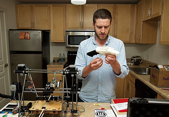
프린트 건미국 비영리단체 디펜스 디스트리뷰트가 인터넷에 공개한 설계도만 있으면 전 세계 누구나 3D 프린터로 이와 똑같은 권총을 만들 수 있다.
ABS 플라스틱 수지2)를 소재로 인쇄된 리버레이터는 38구경 총알을 발사하는 단발 권총이다. 발사 구조나 메커니즘으로 본다면 제대로 된 총이라기보다는 ‘응급 총알 발사장치’라고 부르는 것이 더 적당한 수준이기는 하다. 단적인 예로 이 총에는 다수의 탄약을 저장했다가 급탄해주는 탄창이 없다. 총열에 강선은 파여져 있지만 정확성은 보증하지 못한다. 총 본체가 모두 플라스틱으로 되어 있는 만큼 금속 소재의 권총만한 내구성도 있을 리 만무하다. 권총용 총알 가운데 호신용 권총에 많이 쓰이는 비교적 약한 탄인 38구경을 사용하는 것이 그 방증이다.
미국 위스콘신에 거주하는 조라는 이름의 한 엔지니어가 디펜스 디스트리뷰트의 설계도를 내려 받아 리버레이터를 제작, 9발의 시험사격을 했는데 사격 도중 공이, 나사 등의 부품이 변형되거나 튀어나가 버렸다는 후문이다.
그러나 조잡하기는 해도 분명 총기임에는 틀림없다. 총알이라는 물건 자체가 어떻게든 뇌관만 때려주면 발사되며, 단 한발만 발사가 이뤄져도 살상이 가능하니 말이다. 올 1월호 헤드라인 섹션에 3D 프린터로 아이폰이 복제되는 세상이 올 것이라고 예견한 파퓰러사이언스조차 예상치 못한 급진적 도전이 성공해버린 것이다.
미국 현행법상 DIY 총기 제조는 불법이 아니다. 따라서 미국 내에서라면 리버레이터의 제조 행위는 법적으로 아무런 문제가 없다. 하지만 사안의 심각성과 사회적 파장을 고려한 미 국무부는 지난 5월 8일 미국이 아닌 해외에서도 인터넷을 통해 설계도를 다운로드 받을 수 있다는 점을 들어 국제 무기거래 규정에 어긋난다며 웹사이트에서 설계도를 내리라고 디펜스 디스트리뷰트에 지시했다. 당연히 이 단체는 지시를 따랐지만 이미 10만회 이상 다운로드가 이뤄진 뒤였다.
지금은 진정 국면에 들어서기는 했어도 이번 일이 갖는 상징성은 그야말로 엄청나다. 3D 프린터가 단순히 가정용 인테리어 제작 기계가 아닌 세상을 뒤흔들어 놓을 뜨거운 감자가 될 수 있음이 입증됐기 때문이다.
제품 생산의 민주화
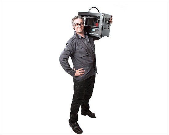
가정용 도깨비 방망이기술 진보에 힘입어 3D 프린터는 책상 위에 올려놓을 수 있을 만큼 작아졌다. 생산의 민주화가 실현될 근간이 마련된 것이다.
D 프린터는 디지털 모델을 사용해 고형소재를 가지고 입체적인 물건을 만들어내는 장치다. 잉크젯 프린터와 동일한 메커니즘으로 원료를 분사해 한 겹씩 적층해나간다는 이유로 3D 프린터라는 이름이 붙었다.
물론 인간은 3D 프린터가 존재하기 이전에도 고형소재로 입체물을 제작해 왔다. 그러나 전통적인 공작 기법은 소재를 절삭하고, 구멍을 뚫는 등 조각을 하는 것에 가까웠다. 그런 탓에 숙련된 기술이 없다면 제대로 된 입체물의 제작이 매우 어려웠다.
반면 3D 프린터는 잉크 역할을 하는 원료 소재와 컴퓨터 소프트웨어로 만든 3차원 설계도만 있으면 누구라도, 어떤 형태의 물건이라도 제작이 가능하다. 그것이 심지어 어린이일지라도.
이러한 3D 프린터의 역사는 생각보다 오래 전으로 거슬러 올라간다. 지난 1981년 일본 나고야시 공업연구소의 연구자였던 고다마 히데오가 원시적인 3D 프린팅 기법으로 최초의 입체물을 제작했다. 현대적 개념의 3D 프린터에 대한 기술적 기반을 확립한 인물은 미국의 연구자 찰스 헐이다. 그는 1984년 스테레오리소그래피(stereolithography)라는 입체 모델링 인쇄 기법을 창안, 1986년 특허를 획득했다.
그 후로 30년 가까이 지난 지금, 웬만한 방 하나 크기에 달했던 3D 프린터가 책상 위에 올려 놓을 수 있을 정도로 소형화됐다. 활용 분야도 보석, 제화, 산업디자인, 건축, 엔지니어링, 건설, 자동차, 항공우주, 치의료, 교육, 지리, 토목 등 산업 전반으로 확대돼 있다.
3D 프린터의 최대 장점은 기존 생산방식과는 비교도 안될 만큼 신속·정확한 제작이 가능하다는 사실이다. 특히 3D프린터를 활용하면 각각의 부품을 별도로 만들어서 제작해야 했던 물건도 아예 조립된 상태로 인쇄할 수 있다. 너무 복잡한 모양을 하고 있어 여러 부분으로 나눠서 만들었었던 부품도 마찬가지다. 그에 맞는 설계도만 확보한다면 말이다.
이뿐만이 아니다. 적층 인쇄라는 점을 이용해 하나의 부품이 여러 색상을 가지도록 만들 수도, 여러 소재로 하나의 부품을 만들 수도 있다.
조립식 프라모델을 가지고 설명한다면 3D 프린팅의 효율성을 더욱 알기 쉽다. 기존의 방식으로 만들어진 프라모델은 부품을 일일이 떼어내서, 다듬고, 본드로 붙여서, 스티커를 붙이는 고된(?) 과정을 거쳐야 완성되지만 3D 프린터는 조립도, 스티커도 없이 완성품 프라모델을 인쇄해낼 능력을 갖고 있다.
이 모든 장점은 아직 제조라인이 구축되지 않아 전 공정을 수작업으로 진행해야하는 시제품을 제작할 때 두드러진다. 덕분에 신제품 개발에 투입되는 비용과 시간, 정력을 대폭 절감할 수 있다.
물론 일반인들의 입장에서 3D 프린터의 등장으로 가장 크게 체감할 수 있는 변화는 단연 제품 생산의 ‘민주화’다. 아직은 모든 물건을 제작할 수는 없지만 이론상 3D프린터는 금형이나 선반, 밀링 머신 같은 값비싼 공작 기계를 보유하지 않은 사람도 제품을 직접 만들어서 사용할 수 있는 길을 열어 놓았다. 가능과 불가능이 아닌 시간의 문제일 뿐이다.
3D 프린터가 열어줄 미래
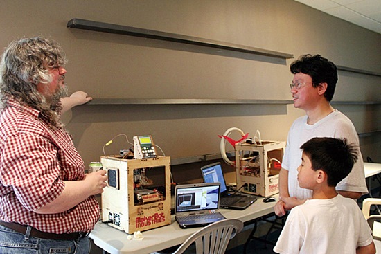
가지고 있는 잠재력이 워낙 방대한 만큼 현 단계에서 3D 프린터가 앞으로 우리에게 어떤 변화를 일으킬지 정확히 예측하는 것은 쉽지 않다. 다만 3D 프린터가 진화해 나갈 방향은 대략적이나마 추정이 가능하다.
우선 3D 프린터로 만들 수 있는 물체의 강도가 비약적으로 향상될 전망이다. 산업용 제품으로 사용해도 무방한 수준까지 다다를 것이다. 지금도 이미 3D 프린터로 제작된 부품이 항공기에 쓰이고 있는 상태며 자동차, 군수품, 전자기기 등에도 3D 프린터 부품의 적용이 늘고 있는 상황이다.
또한 최근 들어 3D 프린팅 된 제품들은 인명을 구하고, 사람들의 건강을 증진시키는 데도 유용하게 쓰이기 시작했다. 뼈 임플란트, 의수족, 교정기구 등의 의료기기가 그 실례다. 원래 인체는 기계와 달리 사람마다 체격과 생김새가 모두 다르다. 일란성 쌍둥이도 예외가 아니다. 이 점에서 환자의 신체를 3D 스캔한 데이터를 토대로 의료기구를 프린팅하면 개별 환자에게 맞춤화된 제품을 저렴하고 빠르게 생산할 수 있다.
이와 맞물려 인체의 세포를 가지고 3D 프린터로 연조직을 인쇄하는 실험도 진행되고 있다. 머지 않아 3D 프린터가 만든 동맥과 정맥이 수술실에 모습을 드러낼 것이며, 언젠가는 환자 자신의 세포로 만든 인공장기를 이식받는 날도 찾아올 것이다.
또한 개별 소비자의 취향에 맞춰 제품을 개량하거나 처음부터 특정 소비자에게 최적화된 소량 주문생산이 일반화될 개연성이 높다. 지금까지 소량 주문생산은 대량생산에 비해 가격경쟁에서 밀려 기피돼 왔지만 3D 프린터의 등장으로 모든 것이 달려졌기 때문이다.
따라서 향후에는 소비자가 온라인으로 자신이 원하는 사양을 입력하면, 기업이 해당 제품을 3D 프린터로 제작해 보내주는 시스템이 활성화될 수 있다. 초기에는 스마트폰 케이스, 귀걸이 같은 액세서리나 인테리어 소품이 주류를 이루겠지만 나중에는 전기밥솥, TV, 냉장고 등의 전자제품까지 그 범위가 확대될 가능성을 배재할 수 없다.
기술 혁신의 촉매제
전문가들은 또 3D 프린터로 인해 제품의 기술혁신 속도도 더욱 빨라질 것이라고 분석한다. 앞서 언급한 대로 3D 프린터는 제품의 설계개발에 드는 시간과 비용을 절감시켜 주기 때문에 개발자들이 연구개발비 걱정에서 벗어나 마음껏 창의성을 발휘하게 될 것이라는 이유에서다.
특히 이 트랜드는 3D 프린터용 설계 소프트웨어의 발전, 3D 프린터용 소재의 다양화에 힘입어 하루가 다르게 가속화될 전망이다. 기존에 없던 신소재를 사용한 혁신제품들이 대량으로 쏟아져 나올 수도 있다. 3D 프린터로만 경제성 있게 제작 가능한 제품들을 대상으로 탄소나노튜브, 인쇄 회로 등이 결합된다면 오늘날의 제품들이 상상도 할 수 없을만큼 대단한 제품들을 만들어 소비자들의 눈을 사로잡을 수 있다.
덧붙여 3D 프린팅 시장의 팽창에 맞춰 신규 비즈니스 모델이 나타날 수도 있다. 어쩌면 프린터를 갖추고 복사를 해주던 학교 앞 문방구들이 3D 프린터를 구매할 형편이 되지 않는 사람들을 위해서 3D 프린터를 들여놓고 간단한 제품을 만들어 줄지도 모른다.
물론 반작용도 없을 수는 없다. 3D 프린터가 대중화되면 원 설계안의 지적재산권이 누구에게 있는지에 대한 논쟁이 뜨거워질 것이다. 기업이나 개인들이 자신의 설계안이 손쉽게 복제될 수 있음을 지각하게 되면 권익을 지키기 위해 치열한 법적 공방도 불사할 것이기 자명한 탓이다. 이는 10여년 전 개인들의 MP3 파일을 공유하는 P2P 사이트가 등장하며 음원의 불법 복제가 만연해 음반사들이 법적 대응을 한 것과 유사하다.
미래학자 앨빈 토플러는 저서 ‘제3의 물결’에서 오늘날과 같은 정보화 사회의 도래를 예견했다. 정보화는 단순히 컴퓨터와 인터넷, 스마트폰에서 끝나는 것이 아니다. 인간 생활의 모든 영역이 정보화의 파도를 얻어맞을 것이며, 인간이 원하는 재화를 만들어내는 제조업도 당연히 그 대상이 된다.
제2의 물결 사회, 즉 산업 사회의 소품종 대량생산 제조업은 조금씩 그 운명을 다해가고 있다. 그 자리를 다품종 소량생산 방식이 무섭게 치고 들어오고 있는 실정이다. 그리고 누구에게나 생산의 기회를 열어주는 3D 프린터는 그러한 상황을 무섭게 부추기고 있다.
21세기형 도깨비 방망이라 할 수 있는 3D 프린터가 가져다줄 미래에 기대와 우려가 교차되는 시점이다.
[MADE IN 3D PRINTER] 3D 프린터의 손재주
3D 프린터는 이미 총 이외에도 놀라운 것들을 많이 만들어내고 있다.
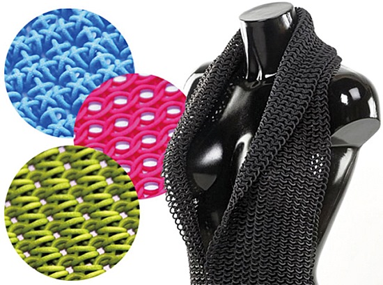
1. 의류
디자이너 지리 에벤휘스와 잔느 키타넨은 재활용 플라스틱을 원료로 3D 프린터를 이용해 이 옷을 만들었다. 기존 방식에 비해 원단 제작 속도가 훨씬 빨랐다는 후문이다.
디자이너 지리 에벤휘스와 잔느 키타넨은 재활용 플라스틱을 원료로 3D 프린터를 이용해 이 옷을 만들었다. 기존 방식에 비해 원단 제작 속도가 훨씬 빨랐다는 후문이다.
2. 건물
이탈리아 발명가 엔리코 디니는 건축물 인쇄가 가능한 대형 3D 프린터를 개발했다. 현재 유럽우주기구(ESA)가 이 프린터를 이용해 달기지를 건설하는 방안을 모색하고 있다.
이탈리아 발명가 엔리코 디니는 건축물 인쇄가 가능한 대형 3D 프린터를 개발했다. 현재 유럽우주기구(ESA)가 이 프린터를 이용해 달기지를 건설하는 방안을 모색하고 있다.
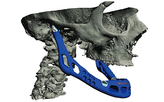
3. 임플란트
환자를 CT 스캐너로 촬영한 뒤 그 데이터로 설계도를 만들면 3D 프린터를 이용해 의수족 등 맞춤형 의료기기 제작이 가능하다. 현재 이식용 턱뼈가 개발돼 있다.
환자를 CT 스캐너로 촬영한 뒤 그 데이터로 설계도를 만들면 3D 프린터를 이용해 의수족 등 맞춤형 의료기기 제작이 가능하다. 현재 이식용 턱뼈가 개발돼 있다.
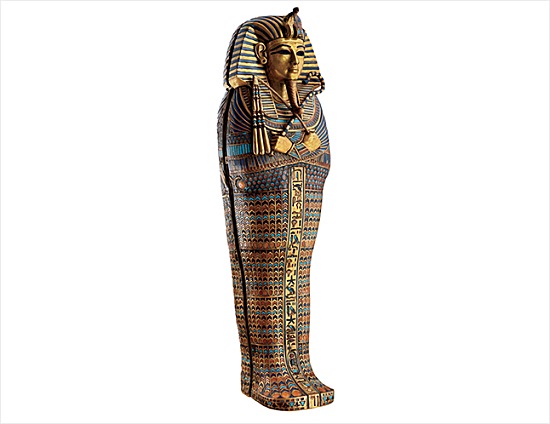
4. 미라
고대 미라는 귀중한 고고학 자료로 훼손의 우려가 높다. 그래서 이집트 연구팀은 투탕카멘 미라를 CT 스캔한 후 3D 프린터로 복제품을 제작, 전시회에 대신 내보내고 있다.
고대 미라는 귀중한 고고학 자료로 훼손의 우려가 높다. 그래서 이집트 연구팀은 투탕카멘 미라를 CT 스캔한 후 3D 프린터로 복제품을 제작, 전시회에 대신 내보내고 있다.
5. 인체 조직
미국 샌디에이고 소재 재생의학기업 오거노보는 인간의 세포를 원료로 인체에 이식 가능한 조직을 프린팅하는 3D 바이오프린터 ‘노보젠 MMX’를 판매 중이다.
미국 샌디에이고 소재 재생의학기업 오거노보는 인간의 세포를 원료로 인체에 이식 가능한 조직을 프린팅하는 3D 바이오프린터 ‘노보젠 MMX’를 판매 중이다.
- 글
- 이동훈
- 과학칼럼니스트 (enitel@hanmail.net)
- 제공
- 파퓰러사이언스 (http://popsci.hankooki.com)

http://navercast.naver.com/magazine_contents.nhn?rid=1697&contents_id=30687
August 15, 2013
Open Source Powder based Rapid Prototyping Machine
Open Source Powder based Rapid Prototyping Machine for Ceramics
A. Buddinga, T.H.J. Vanekera, A.J.A. Winnubstb
http://www.sciencedirect.com/science/article/pii/S2212827113001753
http://www.utwente.nl/ctw/opm/education/de/Afstuderen/Voorbeelden/2012-06-28%20-%20MSc%20Experience%20Alex%20Budding.pdf
https://groups.google.com/forum/#!msg/dhmn-discussion/YneSFIPYe7U/Ka1ff_9VFgcJ
DESIGN AND FABRICATION OF A POWDER-BASED PERSONAL 3D PRINTER
Kory Koyamatsu, Kristina Olson, Erik Roby, Nathaniel Thompson,Tri Truong
http://www.erikroby.com/p3p-finalpaper.pdf
August 14, 2013
AdderFab
https://sites.google.com/site/3dprinterlist/powder-printers/adderfab
Folks we are hosted at a University and we have been on break for the past two weeks. Thus, we haven’t really been doing Open3DP things. However, we are back in session now.
AdderFab is the combined result of three separate Capstone student design teams over a span of over four years. The original name of the project was P3P (personal 3D printer). The original team (Version #1) was composed of Kory Koyamatsu, Kristina Olson, Erik Roby Nathaniel, and Thompson Tri Truong. Their project produced a prototype 3D printer which almost worked. They filed a group report Design and Fabrication of a Powder-Based Personal 3D Printer.
Executive Summary
The objective of this project is to design and prototype an open source, open architecture, powder-based three dimensional printer. During the course of the project a prototype system was manufactured and, during subsequent testing, was found to successfully print objects by applying an organic binder to a multi-mode sugar powder.
The objective of this project is to design and prototype an open source, open architecture, powder-based three dimensional printer. During the course of the project a prototype system was manufactured and, during subsequent testing, was found to successfully print objects by applying an organic binder to a multi-mode sugar powder.
The prototype system consists of three main subsystems: the enclosure, the powder chambers, and the print carriage. The enclosure is made from a set of interlocking acrylic panels that are joined by threaded fasteners. There are three powder chambers, feed, build, and waste, which store powder in its bound and unbound states. Powder for each layer is transferred from the feed to the build chamber using a manual spreader bar after the feed and build piston are moved vertically by a non-captive linear actuator. The print carriage is supported by a pair of rails and is moved over the powder beds by a rack and pinion gear system. Carriage and print head motion is controlled by stock Lexmark Z735 hardware and software, with only minor hardware modifications.
The main strength of this design is the low total cost compared to all other powder printers and even other open source rapid prototyping systems, with an estimated cost for the end user of $1,600. Due to a small number of parts, the availability of drawings, and a limited number of modifications to the print assembly, maintenance is not only possible, it is simple for an end user to perform.
For a first generation prototype, the repeatability, as observed during preliminary testing, seems very promising. Despite the strengths, many aspects of the first generation design could be improved. Adding a return mechanism would be the first step in fully automating the build process. An improved and automated spreader bar would also allow thinner layers. Finally, a more secure method of mounting to the rails would improve the repeatability.
The P3P represents a significant achievement to be realized in ten weeks. The P3P promises an open source system that allows hobbyists, educators, and anyone with an interest in free-form fabrication to experiment with a smaller investment of time and money than any other platform currently allows.
The second team (Version #2) was composed of Steven Balkus, Miguel Guzman, Kevin Hawkinson, Ben Palmer, and Vlad Nesterov. This team continued with the concept of using an existing printer’s carriage. They switched to a LexMark Z715 printer. They filed a group report entitled Personal 3-D Powder Based Printer Version 2.0
Executive Summary
The objective of this project is to design and construct an open source, open architecture, affordable, powder base 3-D printer. During the project a working prototype was constructed, tested and determined to successfully print objects using ink and a sugar based powder.
The objective of this project is to design and construct an open source, open architecture, affordable, powder base 3-D printer. During the project a working prototype was constructed, tested and determined to successfully print objects using ink and a sugar based powder.
The prototype printer consists of six different components: the enclosure, the powder beds, the gearbox, the print carriage, the powder spreader, and the return mechanism. The prototype’s enclosure is constructed of wood using wood screws as fasteners and contains drawer sliders to support the movement of the printer in a smooth manner. There are two powder beds one for the build the other for the fill. The gearbox’s design was constructed to attach to drawer sliders to drive the print carriage over the powder beds. The print carriage is from a Lexmark Z35 printer, and is mounted to the sliders. The powder spreader is the roller part found used in the original printer as a paper feed. The return mechanism uses a belt to drive the printer back to its initial position.
The P3P2 printer achieved most of its goals, but its main strength is that it is an affordable alternative to the 3-D printers available on the market today. It also corrected the printing stability issue that was encountered during the previous P3P project as well as reduced the number of computers required to one. P3P2 added a return mechanism to further automate the process as well as a powder spreader. The P3P2 achieved a lot of the objectives set forth from the initial P3P group, but it still left several areas for future improvement. These areas include aligning the printer properly so that the layers of the parts line up, and also include the self automation of printing a whole part using only one input from the user.
The P3P2 gives a further look into the advancement of the P3P project and some ways to improve upon the initial P3P design, and construct an affordable alternative for the average person to the 3-D printing problem.
Version #3 was created and posted by Kevin Hawkinson (KevinH) on thingiverse. Kevin was a member of the Version #2 team and he choose to stay with the concept of employing an existing printer’s carriage. Version #3 was based on a Lexmark z715 inkjet printer. Kevin went through and cleaned up most of the issues left in Version #2. He has a BOM, Cut files and Model files. Nicely done!
The current team (which created the name AdderFab) was composed of Patrick Hannan, Jared Knutzen, Nicholas C Lewis and Joy Markham. This team started up with a few different constraints (namely that they couldn’t use an existing printer or printer carriage) and that the build space would be 5″x5″x5″ (125mm x 125mm x 125mm). They filed a group report entitled MONO-‐MATERIAL PERSONAL 3D PRINTER
Executive Summary
The goal of this project is to develop a low cost, open source 3D printer utilizing standard inkjet technology,for personal use.
The goal of this project is to develop a low cost, open source 3D printer utilizing standard inkjet technology,for personal use.
The prototype design used a carriage assembly constructed from steel rods that were assembled using connectors that can be printed on an FDM machine. The entire carriage system is driven along the x--axis by a belt attached to a stepper motor. The print cartridge,taken from an HP point of sale printer,is driven along the y--axis by another stepper motor belt drive. Attached
to the carriage frame, a textured powder roller spreads powder from the feed area over the build area. In order to obtain a better surface finish, a DC motor rotates the powder spreader as it moves across the print area.The feed and build chambers are constructed from PVC fence posts. A scissor lift controls the vertical displacement of the piston in the build chamber, while a screw lift controls the piston in the feed chamber. The electronic controls use an Arduino Mega to run all of the printing systems.
to the carriage frame, a textured powder roller spreads powder from the feed area over the build area. In order to obtain a better surface finish, a DC motor rotates the powder spreader as it moves across the print area.The feed and build chambers are constructed from PVC fence posts. A scissor lift controls the vertical displacement of the piston in the build chamber, while a screw lift controls the piston in the feed chamber. The electronic controls use an Arduino Mega to run all of the printing systems.
The design resulted in a working prototype that fulfills all of the design constraints. The rod frame carriage design is lightweight, easy to assemble and easy to integrate with the other systems. The powder spreading system produced a very nice layer thickness and surface finish even before the system could be optimized. The scissor lifts designed for the feed and build areas, reduced the overall height of the printer allowing it to fit in a standard fume hood. The Arduino used in the electronics has a large library of resources available to perform things like LCD, SD card, and stepper control.
Areas where future work should be focused include replacing the y‐axis stepper motor to improve printing speed, making molds and casting printable parts to bring down the overall cost, developing host side software, optimizing the speed of the powder spreading cycle, and modifying the design of the scissor lifts to improve their stability.
The design will have a significant impact in that it will allow 3‐D powder printing to make the jump from the commercial realm into the homes of people around the world. An affordable desktop 3‐D powder printer will let students, artists, hobbyists, and others print objects in their own homes.
Design Constraints:
The following design constraints were identified by the team at the outset of the project:
• Cost: <$300 (<$500 for prototype)
• Size: less than 28”l x 24”w x 28”h
• Open source
• Cost: <$300 (<$500 for prototype)
• Size: less than 28”l x 24”w x 28”h
• Open source
In addition, the Professor imposed the following constraints on the project:
• Utilize inkjet technology
• Cannot use existing printer carriages
• Must use PVC fence post build bed
• Cannot use existing printer carriages
• Must use PVC fence post build bed
The next team has been assembled to take this prototype and productise it to produce an available open source 3D powder printer!
PWDR Model 0.1
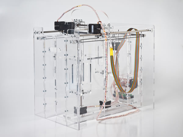
Pwdr Model 0.1
Pwdr is an open source powder-based rapid prototyping machine. Its goal is to promote experiments and innovations in powder-based rapid-prototyping. The machine is ready to use both the 3DP as the SLS process with minimal adaption, although the printer is currently prepped for 3DP.
Hardware
The Pwdr Model 0.1 consists of chassis, tool head and electronics. The printer entirely consists of off-the-shelf components. It has a simple design and can be built within a couple of hours. The machine is easy and affordable to build and modify. Building a Pwdr Model 0.1 machine costs about €1000,-.
Software
The accompanying software for the Pwdr Model 0.1 converts the CAD model in a printable format. This file is then uploaded to the Pwdr Model 0.1 micro-controller. The machine is controlled by easy-to-use software that allow full control of the printing process. The Pwdr Model 0.1 software has been based on open source tools like Arduino and Processing.
Materials
A whole new range of materials become available for experimenting with open-source rapid-prototyping; for example, when using the 3DP process: gypsum, ceramics, concrete, sugar, etc. And when the SLS process is fully supported, plastic materials like ABS, PP, Nylon and metals become available as building material.A Hewlett Packard inkjet cartridge is used for the deposition of binder. The cartridge can be refilled with custom binders using a syringe. A custom binder of 20% alcohol and 80% water has been proven to work.
Specifications
- Maximum build size: 125mm x 125mm x 125mm
- Print resolution (3DP): 96DPI
- Minimum vertical step size: 50μm
- Speed (depending on printed part): ±1 minute per layer
Update (7/8/2012): print results
As this website focussed on the machine and less on the current results. Here are a couple of pictures of the current print results
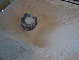
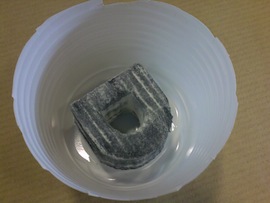
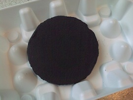
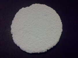
Top left: ZCorp ZP131 (gypsum) with standard inkjet ink in machine. Top right: excavated part. Bottom left: Resin fixated part (ZP131). Bottom right: Sintered alumina membrane (AKP15 + standard ink that is burnt during sintering)
Printing of the top left and right part, the roller is visible behind the cartridge
This work is licensed under a Creative Commons Attribution-NonCommercial 3.0 Unported License. 2012
http://www.thingiverse.com/thing:27794
http://pwdr.github.io/
Subscribe to:
Comments (Atom)


